ELECTROSTATICS, ELECTROSCOPE & CAPACITORS
ELECTROSTATICS
Electrostatics is the study of stationary or slow moving charges (electric charges). Such charges are called static charges (insulators contain static charges while conductors contain free charges). But what is an electric charge? An electric charge is a fundamental component of matter that does not occur in isolation. It is a property of a subatomic particle that causes it to experience a force when placed in an electric or magnetic field.
There are two types of charges:
- Negative charges
- Positive charges
Protons (found in the nucleus of an atom) carry a positive charge while electrons (found in orbits around the nucleus) carry a negative charge. The charges, though opposite, are of equal magnitude. A single (unit) charge, denoted e or q, has one magnitude only of approximately 1.602× 10⁻¹⁹ C. Magnitude of charge, say Q, contained in a body is the integral multiple of the basic unit charge e, that is;

Where

The total charge a body contains is therefore discrete (quantized).
A stable atom carries equal number of electrons and protons. However, atoms in some materials, for example human skin, hair and glass loose electrons easily for example when some mechanical force (such as rubbing) is applied. When atoms loose electrons, they become positively charge which basically means that they have more protons than electrons). Other materials for example plastic gain electrons easily and as such end up with more electrons than protons. Such materials ae said to be negatively charged. Charged materials attract uncharged materials. As an example, a plastic rod rubbed against dry hair attract small pieces of paper; a nylon dress clings on the skin when it rubs against it. Sparks (static electricity) may be observed when the dress is yanked off as a result of charge transfer between the dress and the skin.
Charges exert force on each other known as Coulomb's force. This force has two properties (called the laws of electrostatics);
- Like charges repel
- unlike charges attract
A nylon dress clings on the skin because the rubbing process removes electrons from the skin (making skin positively charged) which are then transferred to the dress (making it negatively charged). Similarly, a plastic comb is better at coming dry hair because the comb and hair attain opposite charges during the combing process (metals contain free mobile electrons and therefore do not get charged, unless completely isolated)
GOLD-LEAF ELECTROSCOPE
An gold-leaf electroscope is a devise used for;
- Detecting the presence of electric charge on a body
- Identifying the type of charge (positive or negative) on a body
- Determining the relative magnitude of charge on a body
Parts of a gold-leaf electroscope

The wall (casing) of an electroscope is earthed. This is to ensure that any negative charge induced in the casing is conducted to the ground, or any positive charge induced is neutralised by charge from the ground. The casing therefore remains neutral at all times hence bearing no effect on the deflection of the gold-leaf. If an electroscope is not charged, the gold-leaf is not diverged. However, if the electroscope is charged, or a charged body is brought close to the electroscope, the leaf diverges. The degree of divergence is proportional to the magnitude of charge on the electroscope (or in the body).
There are two methods of charging an electroscope;
- Charging through contact
- Charging through induction
Charging through contact
The charging process starts by bringing a charged body, say a negatively charged rod, near the cap of the electroscope. As a result of electrostatic force and bearing in mind that like charges repel and unlike charges attract, the negative charges on the electroscope are repelled to the leaf and the plate resulting in leaf divergence, while the positive charges move to the cap. The rod is then brought into contact with the cap. Consequently, some negative charges on the rod enter the electroscope and neutralise some of the positive charges, leaving the electroscope with a net negative charge. When the rod is withdrawn, the negative charges on the leaf and the plate are distributed throughout the electroscope. The leaf divergence reduces as the magnitude of charge reduces.

If a positively charged rod was used instead, the electroscope would have acquired a net positive charge.
Charging through induction
A charged rod, say negatively charged, is brought close to but not touching the cap of the electroscope. The negative charges on the electroscope are repelled to the leaf and the plate (leaf diverges) while the positive charges move to the cap. With the rod still in place, the cap is touched (earthed). Consequently, the negative charges on the electroscope are conducted to the ground leaving the plate and the leaf with no net charge, and the leaf therefore collapses. The earth connection is then removed while the rod is still in place (to prevent the electroscope from discharging). The rod is then withdrawn. The positive charges on the cap are distributed to the leaf and the plate. Consequently, the leaf diverges. The electroscope in this case has a net positive charge.

If a positively charged rod was used instead, the electroscope would have acquired a net negative charge.
Important to note
- An electroscope charged by contact acquires the same charge as the charging object, while one charged through induction acquires a charge opposite that of the charging object.
- When a sharp pin is brought near the cap of a positively charged electroscope, the tip of the pin acquires a negative charge. Sharp points concentrate charge and consequently, the highly charged tip ionises the air around it, attracting the positively charged air molecules and repelling the negatively charged ones to the cap of the electroscope. The negative charges pair up with positive charges on the electroscope thereby discharging it. The leaf therefore collapses.
- The magnitude of charge on a body is proportional to the divergence of the leaf. More charge results in greater divergence and vice versa.
- Say a rounded object, for example a sphere, is brought near the cap of a negatively charged electroscope. The positive charges on the sphere will move to the side closest to the electroscope while the negative charges move to the other end. Some of the negative charges on the electroscope move to the cap leading to a reduction in charge on the leaf and the plate. The leaf divergence consequently reduces.
- A charged electroscope is not devoid of one charge. It just has one charge in excess of the other. A positively charged electroscope has more positive charges than negative charges, while a negatively charged one has more negative charges than positive charges. If for example a positively charged body is brought close to a negatively charged electroscope, the negative charges on the electroscope will move to the cap, while the fewer positive charges move to the plate and the leaf. The leaf will therefore not collapse but the divergence will reduce. Also, if an uncharged body is brought close to a negatively charged electroscope, the negative charges on the electroscope will move to the cap, while the fewer positive charges move to the plate and the leaf. Consequently, the leaf divergence reduces. If on the other hand a negatively charged body is brought close to the cap of a negatively charged electroscope, the few positive charges will move to the cap of the electroscope while the majority negative charges move to the plate and leaf. The leaf divergence will therefore increase.
CAPACITORS
A capacitor is a store of charge. In its simplest form, a capacitor consists of two metal plates with equal but opposite charge Q and at some distance apart. The space between the plates contains an insulator such as air or plastic. The insulator is called a dielectric.

If V be the charging voltage, then;


C is a constant of proportionality called capacitance. Capacitance is also described as the measure of the ability of a capacitor to store charge. A fully charged capacitor has voltage equal to the charging voltage but oppositely directed. The charged capacitor is therefore more like a cell.
Applications of capacitors include:
- Smoothing current
- Use in camera flash
- Use in computer keyboards
- Electronic noise filtering
Charging a capacitor:
To charge a capacitor, the uncharged capacitor and a high resistance resistor are connected in series with a battery, say of potential difference V. The high resistance prevents short-circuiting the capacitor which would otherwise cause a current surge across the dielectric turning it into a conductor. When the switch S is closed and the current I starts flowing, the plate of the capacitor connected to the positive terminal of the cell starts acquiring positive charges, while that connected to the negative terminal starts acquiring negative charges. The positive and negative charges have equal magnitude at all time. As charge builds up on the plates of the capacitor, the potential difference across the plates, Vc increases proportionately.

The sum of the voltage across the capacitor VC and the voltage across the resistor VR is always equal the charging voltage, V, i.e.
 (i)
(i)
We now need to express VR in terms of VC. Suppose Q and I be the charge on the capacitor and current in the circuit respectively at any time. If C be the capacitance of the capacitor and R the resistance of the resistor (C and R are constant), it follows that;
 (ii)
(ii)
 (iii)
(iii)
Now, current is defined as;
 (iv)
(iv)
Using equation (iv) in (ii), and considering that R is constant, leads to;
 (v)
(v)
Using equation (ii) in (v), and considering that C is constant leads to:
 (vi)
(vi)
We now use equation (vi) in equation (i) to obtain;


 (vii)
(vii)
Integrating

 (vii)
(vii)
Where X is a constant.
To find X, we let VC=0 at t=0. Hence;

 (viii)
Using equation (viii) in equation (vii) leads to


 (ix)
(ix)
Obtain exponential of both sides to get rid of the logarithm;
 (x)
(x)
 (xi)
(xi)
A graph of potential difference between the plates VC and time during charging process shows that voltage increases (grows) exponentially with time. The charging process comes to a completion when the voltage across the capacitor is equal to the charging voltage V;


At this point in time, the magnitude of charge on the positive plate of the capacitor is equal to that on the positive terminal the cell, while that on the negative plate is equal to that on the negative terminal. This means that no potential difference exists between the capacitor and the cell and therefore the current ceases flowing (current flows between two points if a potential difference exists between them).
Discharging a capacitor:
Discharging of a capacitor is also done through a resistor for the same reason as when charging. Both the resistor and the capacitor are parallel to each other as shown.

Once the switch is closed, the capacitor starts discharging. Since there is no external power source, then from Kirchhoff’s law;
 (i)
(i)
But

Hence

 (ii)
(ii)
Using the limits t=0 at VC=V (when fully charged, the voltage across the capacitor is equal to the charging voltage) and t=0 at VC=VC then;


 (iii)
(iii)
Obtain exponential of both sides of equation (iii) to get rid of the logarithm;

 (iv)
(iv)
Equation (iv) shows that the potential difference between the capacitor plates VC decreases exponentially with time:

Important to note
NOTE: If we let V be the voltage across a charged capacitor of capacitance C and Q the charge on the capacitor, it can be shown that the energy U stored in a capacitor is equal to:

Using Q=VC leads to;


Capacitance of a parallel plate capacitor
There are different types of capacitors, the simplest being the parallel plate capacitor. A parallel plate capacitor basically consists of two parallel metal plates, each area A, containing equal but opposite charges Q, at some distance d apart and with a potential difference V across the plates. The space between the plates contains an insulator such as air or vacuum of permittivity of free space space ε0 or an insulating medium such as plastic of permittivity εm. The insulator is called a dielectric. An electric field E is also present between the two charged plates (E points from the positive to the negative plate).

For a capacitor with vacuum (or air) as the dielectric, the magnitude E is given by;
 (i)
(i)
The relationship between relationship between E, V and d is given by;
 (ii)
(ii)
Using equation (i) in equation (ii) gives;

 (iii)
(iii)
If C be the capacitance of the capacitor, then from definition
 (iv)
(iv)
Using equation (i) in (iii) leads to;
 (v)
(v)
Suppose instead of vacuum/air, a material (e.g. plastic) of permittivity εm is used as the dielectric. Equation (v) becomes:
 (vi)
(vi)
Where Cm is the capacitance in the presence of the material dielectric.
To fine the general equation of the capacitance of a capacitance, we divide equation (vi) with equation (vii) to obtain the relative permittivity εr, i.e.
.
Hence
 (vii)
(vii)
Using equation (vii) in equation (vi) and dropping the subscript m in C for generalization leads to;
 (viii)
Equation (vii) implies that the capacitance of a parallel capacitor increases when
- a dielectric other than (or in addition to) vacuum is used
- area of the plates is increased
- distance of plate separation is reduced
Capacitor arrangement in a circuit
Capacitors can be connected in a circuit using two basic types of arrangements from which the effective capacitance can be determined;
- Series arrangement
- Parallel arrangement
When capacitors are connected in series, the same charge is stored in each capacitor. This charge is equal to the charge in the circuit. The voltage across the capacitors is however not uniform and is dependent on the capacitance of each capacitor. The sum of the voltage drops across each circuit is equal to the voltage in the circuit. For capacitors in parallel, the voltage across all the capacitors is the same and is also the same as the voltage in the circuit. The charge on on the capacitors is however different depending and is dependent on the capacitance of each capacitor. The sum of the charge on each capacitor is equal to the charge in the circuit.
While circuits can be build with simple series arrangements or parallel arrangements, more complex circuits containing both series and parallel capacitor arrangements can also be constructed. Such a connection is referred to as a combination arrangement.
(a) Capacitors in series
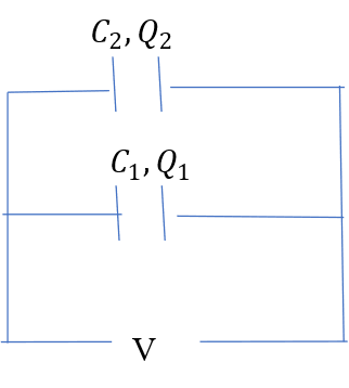
Consider two capacitors A and B of capacitance C1 and C2 respectively connected in series across a power supply voltage V.

If V1 and V2 be the voltage across A and B respectively when fully charged, it follows that:
 (i)
(i)
For capacitors in series, the charge in the circuit is equal to the charge in each capacitor. If Q be the charge in the circuit, then from the definition of capacitance;
 (ii)
(ii)
 (iii)
(iii)
Using equations (iii) and (iiii) in equation (ii) leads to;
 (iv)
(iv)
Considering that V the voltage in the circuit and Q the charge, then the quotient Q/V is equal to effective capacitance C (capacitance in the circuit), hence,
 (v)
(v)
Using equation (v) in equation (iv) leads to:
 (vi)
(vi)
Equation (vi) is used to evaluate the total (effective) capacitance in a circuit containing capacitors connected in series.
Equation (vi) can further be evaluated as follows:


(2) Capacitors in parallel
Suppose the two capacitors are connected in parallel.
The voltage across capacitor A equals the voltage across capacitor B equals the total voltage V in the circuit. The total charge will however be distributed between the capacitors such that;
 (i)
(i)
From the definition of capacitance;
 (ii)
(ii)
 (iii)
(iii)
Using equations (ii) and (iii) in equation (i)

 (iv)
(iv)
The quotient Q/V is equal to the effective (total) capacitance C in the circuit, hence;
 (v)
(v)
Equation (v) is used to evaluate effective capacitance in a circuit containing capacitors connected in parallel.
(3) Combined series and parallel arrangement
To find the effective capacitance, find the effective capacitance of each section then rearrange in such a way that the effective capacitances fall in series arrangement or a parallel arrangement, whichever is easier.. For example;

0 Comment(s)